SUMÁRIO
INTRODUCTION
The testing platform was developed with low-cost hardware (ARM, FPGA), giving the platform a big differential. Moreover, the environment tests both software (JAVA, ATPG) and hardware. For testing hardware, the environment emulates the circuit in a FPGA with the aim to prove the simulated tests in a real environment. Another important difference is the integration of the simulation environments, allowing testing in software as well as in hardware.
VLSI (Very Large Scale Integration)
With the growing complexity of VLSI (Very Large Scale Integration) circuits and SOC (System-on-Chip), the generation of tests has become one of the most complicated and timeconsuming tasks in the field of integrated circuit designing. The more complex the electronic systems become, the more important their verification and testing become.
An integrated circuit during its production process is subject to different types of tests. One of the most widely used test is the structural test, based on failures [2], which allows for a quantitative measure of the fault coverage in the circuit. The proposed platform was used for testing digital circuits.
TESTING OF DIGITAL CIRCUITS
The proposed platform was implemented in Java and uses two additional EDA (Electronic Design Automation) tools to test the circuits. It is possible to divide the platform in software and hardware testing.
In testing software it is possible to use algorithms to test the circuit if there is a description of it. For the hardware test we developed a low-cost platform using an ARM microprocessor and a FPGA. Both tests in software and in hardware aim at identifying circuits that work properly.
In both cases test vectors are applied at the inputs of the circuit and their outputs are analyzed. A major challenge is to achieve a reduced set of vectors that can achieve a large coverage for the circuit. On hardware testing the environment emulates the circuit in an FPGA to test the simulation in a real environment.
RELATED WORK
This section describes some related work on testing of digital circuits. The use of FPGA to test circuits is shown by Kocan [3]. He shows the number of times it is possible to increase the speed (speed up), using the emulation in hardware compared with the analysis in software. Kocan has shown a method to emulate combinational and sequential circuits to detect stuck-at faults. His method shows the analysis of failures using hardware.
Ellervee [4] also showed an increase in the emulation speed when compared to the analysis of faults in software. However, Ellervee showed analyses only for combinational circuits. Schneider [5] showed an environment that incorporates several tools for testing circuits using Java.
FUNDAMENTAL CONCEPTS – ATPG
To test the circuits we used structural testing, which depends on a specific structure (logic gates, netlist) of the circuit. One of the major advantages of structural testing is that it allows to aggregate or improve different algorithms. These algorithms are based on the fault models [6].
An EDA tool was used for the automatic generation of test vectors. In the testing of integrated circuits, the automatic generation of vectors is known as ATPG (Automatic Test Pattern Generation). The generation of the structural test can only happen if the gate-level model (netlist) is available [7].
STRUCK-AT FAULT MODEL
If you have this information, a high coverage rate of failure is possible with a small amount of vectors. The modeling of failure is closely linked to the modeling of the circuit. The stuck-at fault model is the model most used in testing of digital circuits [6].
Logical faults are modeled as stuck-at faults. One stuckat fault forces a fixed value (0 or 1) for a signal line of a circuit, where the line can be an input or an output of a gate or flip-flop [8]. This stuck-at can be a stuck-at-1 (s-a-1) or a stuck-at-0 (s-a-0). This model is simple and independent of the technology used. A circuit may have several stuck-at faults and a signal line of a circuit can have a s-a-0, s-a-1 or be faultfree.
A circuit with n input lines can have 3^(n-1) possibilities of stuck-at lines. Then, for a circuit of moderate size it is possible to have a large number of stuck-at faults. Therefore it is a common practice to consider only the single stuck-at fault model. This model assumes that only one entry or exit of a gate or flip-flop can be s-a-0 or s-a-1. The maximum number of single stuck-at faults for a circuit with n lines is 2*n [6].
The number of failures, using the single stuck-at fault model is considerably reduced. Analyzing Figure 1, there is a NAND gate with an A entry with the s-a-1. This entry always remains at logical 1 level, resulting in a short circuit for the logical level 1. The output of NAND is 0 when the input B is 1 and when the s-a-1 in A is present. If this circuit did not have the s-a-1 or s-a-0, i.e. it would be considered fault-free and the output of this circuit would be 1 for the inputs shown in Figure 1.
So if input A = 0 and B = 1, it is possible to test the s-a-1 in A, because there is a difference in the outputs of the fault-free circuit and faulty gate [9].
nand
Figure 1. NAND Logic gate
GENERATING TESTS FOR DIGITAL CIRCUITS
The analysis of a digital circuit requires a mathematical model to represent it. The mathematical model used in this work is the SSBDD because the Turbo Tester tool [10] uses it and because it is a well accepted model [11] [12].
In addition to the mathematical model chosen to represent the circuit, it is necessary the model of the type of faults to be tested. With the mathematical model chosen and the failure simulation model, the automatic generation of vectors is the ideal way to achieve an efficient test procedure for a given circuit.
The automatic generation of tests attempts to achieve the maximum fault coverage using test vectors at the input and analyzing the outputs of the circuit. The generation of test vectors in the digital domain, was made through algorithms.
D ALGORITHM
The D algorithm proposed by Roth [13] – a pioneer in these tests, – is the basis of the algorithm PODEM [14] used in this work. In addition to this algorithm, the algorithms GENETIC [15] [6] and RANDOM [16] were also used. The fault simulation is the modeling of the circuit in the presence of faults. By comparing the response of the faulty circuit with the circuit without faults, using the same test vector, we can determine the faults detected by the vector [17].
The simulation of faults categorizes the faults in a circuit as detectable or undetectable. A list of all the faults is made with the single stuck-at fault model, withdrawing the equivalent faults as shown in Figure 2.
equivalencias3Figure 2. Fault equivalence
The simulation is initialized with the verification vectors provided and produces a list of faults. The coverage of these faults is measured by the number of detected faults and the total list of faults, as shown in equation 1.
Coverage analysis = Quant. of f. detect/Tot. failures (1)
When you see a high coverage of faults, the simulation can end. If there are vectors that cannot be simulated, they can be removed to reduce the number of test vectors in the list. However, if the test vectors do not produce an adequate coverage according to the equation 1, some of these failures not detected in the list of failures can be passed to a testing program to produce new vectors [6].
A circuit C () is free of faults and circuits C (f(1)) to a C (f(n)) are copies with faults inserted in them. The same vector is applied to all circuits and the outputs of the faulty circuits are compared with the faultfree circuit, as shown in Figure 3.
Figure 3. Fault simulation
ARCHITECTURE PROPOSAL (ARM AND FPGA)
One of the problems of testing integrated circuits is that an ATE (Automatic Test Equipment) is typically very expensive. To minimize the cost impact of testing, a low cost testing platform was developed, as shown in Figure 4. This platform can be divided into two: software testing and hardware testing. A front-end platform was developed in Java for the two types of tests. With regard to software we used Leonardo Spectrum and Turbo Tester together with Java.
The version of the Turbo Tester uses different algorithms to test and analyze the circuits, but does not have a GUI (Graphical User Interface) environment. The tool developed in Java covers the gap. As for hardware, we used a microcontroller of the ARM family and an FPGA to emulate the hardware. The ARM was chosen due to its high processing capacity.
plataformaFigure 4. Proposed architecture
ISCAS BENCHMARK
To test a circuit we must have it initially described in HDL (Hardware Description Language) language. We used the ISCAS85 benchmark circuits for the validation of our proposal. After the application in Java (Figure 5), we convert the HDL description of the DUT (Device Under Test) into a netlist. In order to do this the Java platform accesses the Leonardo Spectrum program, which synthesizes the circuit producing a netlist. The resulting netlist represents the gatelevel model of the circuit and is stored in an EDIF format file.
A library containing the description of the primitive logical gates of the circuits was then developed for each EDIF tested. The Java tool is used to access the Turbo Tester program, the library of primitives, and to convert the EDIF file in an SSBDD file. This file is a logical representation of the digital circuit to be used for the simulation of the circuit. With these files converted to SSBDD it was possible to use the Turbo Tester tools to make the simulations.
Figure 5. Program developed in Java
ACCELERATE THE SIMULATION
To accelerate the simulation and make a real hardware analysis, one can use an FPGA to emulate the DUT as shown in Figure 4. The Java tool sends the testing vectors through a network socket2 to the ARM microcontroller. Figure 6 shows the communication using socket.
Figure 6. Communication between ARM and microcomputer using socket
The socket was implemented in Java in the server computer and in C language at the ARM (Client). The ARM receives and serializes the data and inputs it into the FPGA through an I/O pin. This technique to serialize the data was used because some testing circuits have many more entries than the available I/O pins at the ARM. In the FPGA, the data are received and deserialized by a shift register as shown in Figure 7a. This shift register is synchronized by the ARM clock.
After that, the data are injected into the circuit and received by another shift register, which serializes the data back as shown in Figure 7b. The ARM receives the data and sends the results of the circuit tests by socket back to the Java tool, which compares these vectors with fault-free vectors and classifies the circuit as good or bad. In the Figure 7 the DUT being tested is the circuit C17 of the ISCAS85 benchmark.
Figure 7. Architecture of the DUT
The testing tool has a graphical environment to analyze circuits. The results are shown in two types of graphs. The first is the bar chart, which can be used for the measurement of the generation time of test vectors.
arm_fpga_analisadorFigure 8. Experimental setup
It makes possible to compare different circuits and to use different algorithms as shown in Figure 9. This figure shows, the test of 3 different circuits, applied to each circuit. It is also possible to analyze the coverage of a circuit according to the number of vectors tested, as shown in Figure 10. This figure gives an analysis of coverage of the c432 circuit as the number of vectors.
tempoFigure 9. Analysis of time
EXPERIMENTAL RESULTS
In this section we investigate the time required to test circuits in software and hardware. ISCAS85 benchmarks were used for the testing and the ISE 9.1(Xilinx) was used for the synthesis of circuits for the FPGA. The synthesized circuit is implemented in a Xilinx’s Spartan 3 [18] with 50 MHz of clock speed. The ARM used in the hardware to inject the signals in the FPGA is the Cirrus Logic EP9302 [19] with 200 MHz of clock speed.
coverage
Figure 10. Coverage analysis
Coverage analysis Table I shows the analysis in software for the ISCAS85 benchmark circuits. The simulation was performed on a Pentium 4, 3GHz with 512MB of RAM. In this table we can see the circuits and their respective simulation times (T) and the rate of coverage according to the algorithm used. This time takes into account the time the Java platform takes to access the Turbo Tester, plus the time the Turbo Tester tool takes to analyze the circuit. Thus, the coverage is the same as that achieved by the Turbo Tester tool, but the time will be the sum of the times of the two tools.
Table I
FAULT COVERAGE AND TIME SIMULATION
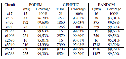
Table II shows the initial results for the emulation in hardware. The vectors that are used in hardware tests are the same used in software tests, and are transferred by socket in the Java tool. Thus, the hardware tests do not have the test vector generator, and the analysis of the outputs of the emulated circuits are made in the Java platform.
We can see that there is less time in Table II, as compared the same circuit and algorithms shown in Table I. This is because the tests in hardware are faster than in software, despite the fact that the hardware does not have the vector generator. It should be noted however that the time seen in Table II takes into account the time to send and receive data by socket, the time the ARM takes to process the DUT input and output data, and the time to propagate it through the DUT.
Table II
TIME EMULATION
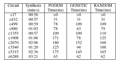
Figures 11 and 12 compare the testing of the ISCAS85 benchmark circuits in software and hardware, respectively.
Figure 11. Analysis of time in software
Figure 12. Analysis of time in hardware
This paper introduces a new platform for testing combinational circuits. A big difference of this platform is that it uses only low-cost components. Another major difference is the integration of several tools for software and hardware testing.
REFERENCES
[1] M. HANSEN et al., “Unveiling the ISCAS-85 Benchmarks: A Case Study in Reverse Engineering,” IEEE DESIGN & TEST OF COMPUTERS, pp. 72–80, 1999.
[2] M. Lubaszewski, E. Cota, and M. Krug, “Teste e Projeto Visando o Teste de Circuitos e Sistemas Integrados,” REIS, RA da L.(Ed.) Concepção de Circuitos Integrados, vol. 2, pp. 167–189, 2002.
[3] F. Kocan and D. Saab, “Dynamic Fault Diagnosis of Combinational and Sequential Circuits on Reconfigurable Hardware,” Journal of Electronic Testing, vol. 23, no. 5, pp. 405–420, 2007.
[4] P. Ellervee, J. Raik, and V. Tihhomirov, “Environment for Fault Simulation Acceleration on FPGA.”
[5] A. Schneider et al., “Internet-based Collaborative Test Generation with MOSCITO,” in Proc. of DATE02, pp. 4–8.
[6] M. Bushnell and V. Agrawal, Essentials of Electronic Testing for Digital, Memory, and Mixed-signal VLSI Circuits. Kluwer Academic, 2000.
[7] D. Gizopoulos and Y. Paschalis, A.; Zorian, Embedded Processor-Based Self-Test. Dordrecht, The Netherlands: Kluwer Academic Publishers,
2004.
[8] I. Berger and Z. Kohavi, “Fault Detection in Fanout-Free Combinational
Networks,” Transactions on Computers, vol. 100, no. 22, pp. 908–914, 1973.
[9] P. Lala, Digital Circuit Testing and Testability. Academic Pr, 1997.
[10] G. Jervan, A. Markus, P. Paomets, J. Raik, and R. Ubar, “Turbo Tester: A CAD System for Teaching Digital Test,” Microelectronics Education,
pp. 287–290.
[11] A. Jutman, J. Raik, and R. Ubar, “SSBDDs: Advantageous Model and Efficient Algorithms for Digital Circuit Modeling, Simulation & Test,” in Proc. of 5th International Workshop on Boolean Problems (IWSBP’02), pp. 19–20.
[12] A. Jutman, “On SSBDD Model Size & Complexity,” in Proc. of 4th Electronic Circuits and Systems Conference (ECS’03), pp. 11–12.
[13] J. Roth, “Diagnosis of automata failures: A calculus and a method,” IBM
Journal of Research and Development, vol. 10, no. 4, pp. 278–291, 1966.
[14] P. Goel, “An implicit enumeration algorithm to generate tests for combinational circuits,” IEEE Transactions on Computers, vol. 30, no. 3, pp. 215–222, 1981.
[15] D. Whitley, “A genetic algorithm tutorial,” Statistics and Computing, vol. 4, no. 2, pp. 65–85, 1994.
[16] S. Mourad and Y. Zorian, Principles of Testing Electronic Systems. Wiley-Interscience, 2000.
[17] M. Cilleti, Advanced digital design with the Verilog HDL. Prentice Hall, 2002.
[18] Spartan-3 FPGA Family: Introduction and Ordering Information, ds099-
1.pdf, Xilinx, 2004.
[19] EP9302 Data Sheet, EP9302_PP3.pdf, Cirrus Logic, 2005.
